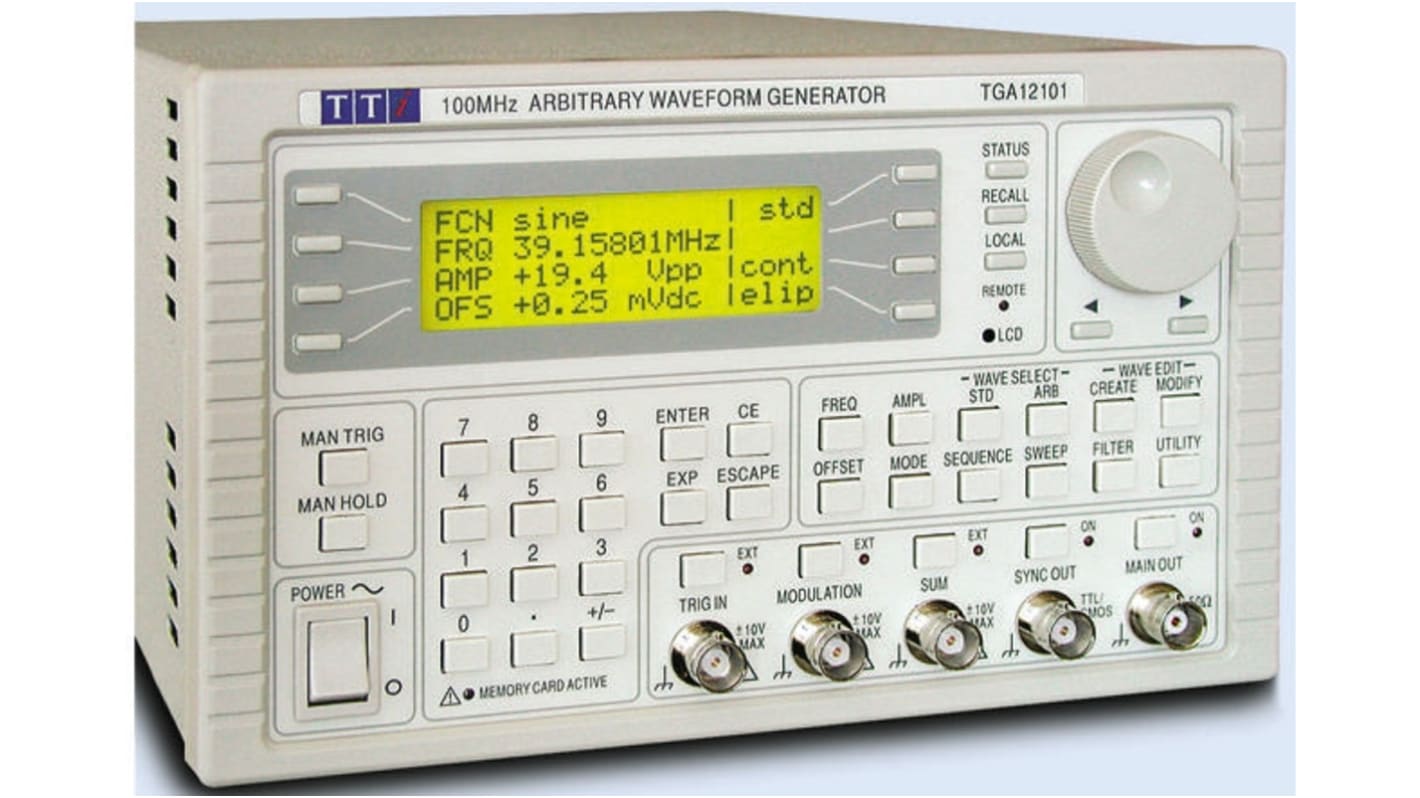
Prijs Each | ||||
|---|---|---|---|---|
|
U bent momenteel niet ingelogd,
Inloggen
In voorraad - levertijd 2 à 3 werkdagen.
| ||||
|
|
|
Specificaties
| Digital Amplitude and Offset | Yes | |
| Digital Frequency | Yes | |
| Dimensions | 335 x 212 x 130mm | |
| Height | 130mm | |
| Input Impedance | 10 kΩ | |
| Interface Type | GPIB, RS232, USB | |
| Internal and External Amplitude Modulation | Yes | |
| Internal Linear and Log Sweep | Yes | |
| Length | 335mm | |
| Maximum Frequency Range Sinewave | 40MHz | |
| Maximum Frequency Range Square Pulse and Arbitrary Waveform | 50MHz | |
| Maximum Frequency Range Triangle/Saw | 500kHz | |
| Maximum Operating Temperature | +40°C | |
| Minimum Frequency Range Sinewave | 0.1MHz | |
| Minimum Frequency Range Square Pulse and Arbitrary Waveform | 1 MHz | |
| Minimum Frequency Range Triangle/Saw | 0.1MHz | |
| Minimum Operating Temperature | +5°C | |
| Model Number p | TGA12101 | |
| Output Amplitude | 20V Pk-Pk | |
| Output Impedance | 50 Ω, 600 Ω | |
| Plug Type | Type C - European Plug, Type G - British 3-pin | |
| Time Base Accuracy | ±10ppm | |
| Variable Sweep | Yes | |
| Weight | 4.2kg | |
| Width | 212mm |
Vind producten die wellicht beter op uw wensen aansluiten door uit de bovenstaande specificaties te kiezen en op 'Meer' te klikken.
MEER
TGA12101, TGA12102, TGA12104
TGA12101, TGA12102, TGA12104 - 100MS/s, 40MHz
'Universal signal source - ARB/Function/Pulse; 1, 2 or 4 channels
Up to 100MS/s sampling frequency
1M points maximum horizontal resolution
True variable clock architecture eliminates jitter
Sinewaves to 40MHz, squarewaves to 50MHz
12-bit vertical resolution with high waveform purity
Pulse train generator for up to 10 pulses of variable width, delay & level
Up to 10 digits of frequency resolution
Inputs for external reference and Arb. clock
Non-volatile storage for up to 500 waveforms and 500 set-ups using CF memory cards
Waveform linking, looping and sequencing
Extensive range of modulation modes
Integral RS 232, USB and GPIB interfaces for remote control and waveform downloading
Built-in basic waveform creation and editing tools
Sophisticated waveform creation and editing via Windows-based software provided
| STANDARD WAVEFORMS | |
| Sine, Cosine, Haversine, Havercosine | |
| Range: | 0.1mHz to 40MHz |
| Resolution: | 0.1mHz or 10 digits |
| Square | |
| Range: | 1mHz to 50MHz |
| Resolution: | 1mHz or 8 digits |
| Triangle, Ramps and Sin(x)/x | |
| Range: | 0.1mHz to 500kHz |
| Resolution: | 0.1mHz or 10 digits |
| Pulse and Pulse Train | |
| Repetition Range: | 40ns to 100s |
| Pulse Resolution: | 8 digits |
| Pulse Delay: | -99.99s to 99.99s |
| Pulse Width: | 10ns to 99.99s |
| Pulse trains of up to 10 pulses may be specified, each pulse having independently defined width, delay and level. | |
| ARBITRARY WAVEFORMS | |
| Arbitrary waveforms are produced using a variable clock technique rather than DDS. This eliminates sampling jitter and allows waveform linking, sequencing and looping. Up to 500 user defined waveforms may be stored per CF card. Waveforms can be defined by front panel editing controls or by downloading of waveform data via RS232, USB or GPIB. | |
| Waveform Memory: | 1048576 points max. (8 min.) |
| Vertical Resolution: | 12 bits (4096 points max.) |
| Waveform Sequencing | Up to 1024 waveforms may be linked. Each waveform can have a loop count of up to 32768. A sequence of waveforms can be looped up to 1048575 times or run continuously. |
| Sample Clock Range: | 0.1Hz to 100MHz (8 digit resolution) |
| Noise Function: | Digital noise generated by 35 bit linear feedback register at 100MHz |
| Output Filter: | Selectable between 40MHz Elliptic, 20MHz Bessel or none |
| WAVEFORM CREATION AND EDITING | |
| Internal: | Built in line drawing, point and waveform insertion and scaling. |
| External: | Software providing a wide range of tools including equation editor and freehand drawing. |
| OUTPUTS | |
| Main Output | |
| Amplitude: | 5mV to 20V pk-pk emf from 50Ω |
| Amplitude Flatness: | ±0.2dB to 1MHz; ±0.4dB to 40 MHz |
| DC Offset: | ±10V |
| Rise and Fall Times: | <8ns |
| Sync Out | |
| Multifunction output user definable to be any of the following: Waveform Sync; Position Markers; Burst Done; Sequence Sync; Sweep Sync; Trigger Signal; Phase Lock Out. | |
| INPUTS | |
| Trig In, Modulation In, Sum In, Hold In, Reference In/Out, Arb Clock In. | |
| MODULATION MODES | |
| Sweep | |
| Linear or logarithmic sweep is provided for both standard and arbitrary waveforms. Frequency span can be from 1mHz to 40 MHz in one range, phase continuous, with independent setting of start and stop frequency. The sweep time is variable between 1ms and 999s and there is a variable sweep marker. The sweep may be free run or triggered manually from the keyboard or externally from the trigger input or remote interface. | |
| Amplitude Modulation: | AM or SCM modulation using the external signal input |
| Burst, Gated and Tone Switching | |
| Standard and arbitrary waveforms can be used in Triggered Burst, Gated or Tone Switching modes. The trigger source can be internal from keyboard trigger generator, or external from TRIG IN or remote interface. For tone switching, a list of up to 16 frequencies from 1mHz to 40MHz can be generated with instantaneous switching between them. | |
| Trigger Generator | |
| Internal source 0.005 Hz to 100kHz squarewave adjustable in 10μs steps. 3 digit resolution. Available for external use from SYNC OUT socket. | |
| MULTI-CHANNEL OPERATION (TGA12102 528-3137 / TGA12104 528-3143) | |
| Channels can be operated independently, as if they were separate generators. A "copy" key allows the settings of any channel to be instantly copied to another. In this mode, the only fixed relationship is that all frequencies are derived from a common reference oscillator. Alternatively, inter-channel relationships of modulation, summing, triggering, or phase locking can be set up. | |
| Inter-channel Modulation | |
| The waveform from any channel may be used to Amplitude Modulate (AM) or Suppressed Carrier Modulate (SCM) the next channel. Alternatively any number of channels may be Modulated (AM or SCM) with the signal at the MODULATION input socket. | |
| Inter-channel Analogue Summing | |
| Waveform Summing sums the waveform from any channel into the next channel. Alternatively any number of channels may be summed with the signal at the SUM input socket. | |
| Inter-channel Phase Locking | |
| Two or more channels may be phase locked together. Each locked channel may be assigned a phase angle relative to the other locked channels. Reference and Sync signals can be used to phase lock two instruments where more than 4 channels are required. | |
| Inter-channel Triggering | |
| Any channel can be triggered by the previous or next channel. The previous/next connections can daisy chain a trigger signal from a start channel, through a number of channels in the chain to an end channel. Complex and versatile inter-channel trigger schemes may be set up. | |
| INTERFACES | |
| Full remote control facilities and waveform download are available through the RS232, USB and GPIB (IEEE-488) interfaces. | |
| Memory Card Interface: | Compact Flash slot, 32MB to 1GB sizes supported |
| Stored Settings: | 500 instrument set-ups plus 500 arbitrary waveforms per card |
| GENERAL | |
| Power: | 230V, 115V or 100V ±14%. 50/60/400Hz, Installation Category II. |
| Size and Weight: | 212 x 130 x 335 mm 4.2 kg (TGA12101 480-0337) 350 x 130 x 335 mm 7.8 kg (TGA12102 528-3137/TGA12104 528-3143) |
Supplied with
Mains lead; Waveform Manager Plus editing/creation software; 64MB CompactFlash card; USB card reader; support CD; instruction manual.

