|
What is a breadboard?
The term ‘breadboard’ has two common meanings today, each quite distinct from the other; unsurprisingly, on this site we’re not going to be talking about a wooden surface for slicing a loaf on.
In modern electronics and engineering circles, a breadboard refers to a (usually) solder-free, plug-and-play platform allowing for speedy insertion and removal of electrical components in circuit-building applications.Breadboard kits today are a very popular toolbox product among electronics professionals, enthusiasts and hobbyists alike. Interestingly, both meanings of the word ‘breadboard’ originally referred to the exact same object, i.e. the simple wooden slabs still used for cutting bread in kitchens around the globe:
-
-
-
Literal kitchen breadboards were what electronics technicians and dabblers once used as a basic platform for initial circuit prototyping and design, allowing them to build and revise temporary versions of a functioning circuit from a makeshift network of wires looped around metal pins (often simple nails or screws).
-
Modern solderless breadboards for electronics are really just an updated, purpose-designed and much more user-friendly version of the same general concept, but with circuit connectivity already built in.
-
-
Uses of breadboards
Again, the key feature of modern electronic breadboards is that they typically don’t require components to be soldered in place. Their connections are therefore temporary, meaning that users can switch them in and out very quickly and easily if they need to revise or correct something.
As noted in the introduction to this guide, by far the most common function of a breadboard in everyday use is in prototyping applications.
-
-
-
The fact that solderless breadboards don’t require circuitry components to be affixed semi-permanently to the surface of a PBC makes it much easier and quicker to manoeuvre and swap them until you achieve the desired effect.
-
This is ideal for both experimental design and rigorous testing of electrical circuits, where the hot-swappable component functionality of breadboards makes them a hugely convenient piece of equipment in the prototyping stages of circuit design and development.
-
-
As well as being considerably more economical in terms of both time and expense, breadboard usage has the added advantage of making diagnostic and debugging work far more straightforward.
-
-
- Solderless breadboards are great for use in technical analysis applications, where ‘breadboarding’ a circuit allows electrical engineers to quickly replicate a real-world PCB found in an existing product or system.
-
This can be especially useful in helping identify likely points of electronic fault or failure in a given circuit, without having to waste time and money making incremental or experimental adjustments to a fully soldered board in a complete but malfunctioning product.
- A single misplaced lead in a sprawling and complex circuit can cause the entire system to behave oddly (or to often stop working altogether), so it’s extremely useful to be able to see exactly where each component pin is going without any guesswork or incorrect soldering slowing things down!
-
Breadboard layout
For anyone already familiar with the fundamentals of printed circuit boards (PCBs), the basic layout of a solderless breadboard will make a lot of sense. For those new to the format, however - and breadboards are especially popular tools among beginner electronics enthusiasts - they can look a little confusing at first.
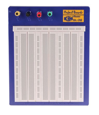
Essentially, a standard empty breadboard is a very simple piece of electronic mounting equipment, consisting of a rectangular plastic platform covered in multiple rows of small, densely-packed holes.
-
-
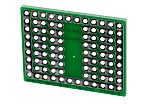
- Compatibility of components is important here: components are generally sold as one of two types, either ‘surface-mount’ or ‘through-hole’.
- Unlike surface-mount versions, through-hole components don’t need to be soldered directly to the face of a PCB in order to make a connection.
- Solderless breadboards are therefore only designed to work with components that have through-hole pins.
-
Breadboard diagrams are commonly used in instructional manuals and educational guides, for demonstrating how to wire up particular types of circuits or components to achieve a specific result. There are numerous versions of breadboarding diagram software available online, most of which do largely the same things - if you’re just starting out with electronic breadboards, find one that works for you and go from there.
In the following sections, we’ll outline what’s going on under the hood of a solderless breadboard, and explore how they can offer an extremely useful starting point for all manner of electronic prototyping and diagnostics projects.
How breadboards work
As we’ve noted already, solderless breadboards are:
-
-
- Great for both learning how to build circuits, and for practical testing and diagnosis applications.
- Commonly used as prototyping platforms in projects to see how a circuit behaves under certain input conditions and connections.
- Ideal for testing out ideas as preliminary models before moving on to building a fully soldered version on a PCB.
-
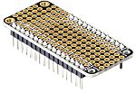
So how does a breadboard work to achieve all this, exactly? Well, running beneath the many rows of small holes for component pins are a number of metal stips - essentially the wires of a circuit - arranged in multiple series.
These wires are what the component legs make contact with when they’re pushed through the holes in the surface of the breadboard. The example below shows the reverse side of a typical breadboard: 
The two sets of parallel wires running horizontally down each long side are the positive and negative power rails (sometimes called buses).
-
-
- Functionally, these are exactly the same as all the other wires in the unit, except each one is connected along its full length.
- These buses are how external power - usually coming from an attached battery pack or similar - is fed to the breadboard and carried to all areas of a prototype circuit.
- If these power rails need to be connected up differently to the stock arrangement for specific types of circuits, you can buy sets of smaller detachable jumper wires to achieve this.
-
In between the power rails, you’ll see several columns of shorter perpendicular wires, or terminal strips, occupying most of the breadboard underside. (In the example above, note the wider gap down the very centre, between the two mirrored sets of columns.)
-
-
- Wires in different columns and rows are generally not connected to one another, and never across either side of the wider central gap; in electronics terms, they’re isolated by the empty space in the middle.
- Each of these terminal strips incorporates a series of five small clips, corresponding to a row of five holes on the surface of the breadboard.
- These clips are what grasp the leads of a component as it’s pushed through the breadboard’s surface holes, thus removing the need for soldering anything in place. Components will be held firmly enough to remain seated when the breadboard is moved around, but will be easy to remove with a light pull.
-

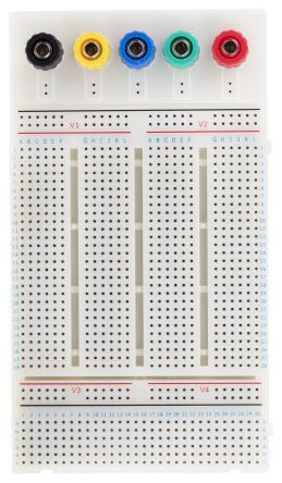
When viewing most mid-sized and larger breadboards the right way up, you’ll usually find that a simple numbering and lettering system has been assigned to the various rows and columns of holes.
-
-
- As noted above, holes in the same row AND column are usually connected by the wires beneath, but not typically across different rows and columns: for example, holes 1A-1E will usually be connected to each other, but not to holes 2A-2E, and so on.
- The alphanumeric grid system functions much like any spreadsheet (or, if you prefer, like the grid in a game of battleships), making it easy for circuit builders to keep track of precisely what’s connected where as they continue to add additional components,
- In turn, planning ahead and troubleshooting becomes much simpler as the circuit starts to grow in size and complexity.
- This system also provides a handy way for beginners to follow basic step-by-step instruction guides when learning to construct elementary circuits using examples and exercises.
-
Types of breadboards
More or less all modern solderless breadboards are set up and laid out to function in fundamentally similar ways. That said, there are five basic breadboard configurations that you’re likely to find on sale from most suppliers in the UK and elsewhere - these are sometimes catalogued as Full+; Full; Half+; Half; and Mini.
As you’d probably expect, the key difference between each of the board types listed above is in their overall size (although the precise dimensions of any breadboard are not universal, and will vary to some extent from manufacturer to manufacturer).
-
-
- In each case, there may be slight differences in exactly how the different rows and columns of wire strips are connected to (or isolated from) one another, but the same general principle will apply across all the above models.
- For the most part, you’ll be able to build any kind of solderless prototype circuit on any size of breadboard.
- If a single board doesn’t provide enough physical space to create the entire circuit you want to prototype, it’s a fairly common feature among various models of breadboard to allow for linking of multiple units.
- Where offered, this means you can connect more than one solderless breadboard together at a time, theoretically giving you as much space as you like for creating progressively more complex projects.
- In each case, there may be slight differences in exactly how the different rows and columns of wire strips are connected to (or isolated from) one another, but the same general principle will apply across all the above models.
-

How to use breadboards
The nature of circuit-building inherently dictates that there is no one correct method for using a solderless breadboard - but there are countless incorrect ways.
-
-
- Naturally there are some fundamental and completely universal ‘rules’ to observe when it comes to designing circuits and connecting different types of components together, but in terms of the overall project, what’s ‘correct’ in any given scenario will depend largely on what it is you’re trying to get the circuit to do.
-
That said, it pays to keep a few general rules of thumb in mind when using breadboards to build a functional circuit prototype. Below you’ll find a list for beginner electrical engineers - assembled in no particular order - of things to keep an eye on as you go:
-
-
- Remember that breadboard circuits aren’t generally appropriate setups for permanent installation as part of any product or device, no matter how rudimentary - they should only be used for designing and testing circuits outside of cases and housings, before you move on to a soldered version.
- While you won’t typically need any tools at all to build a circuit on a solderless breadboard, it can be enormously helpful to have some tweezers or needle-nose pliers to hand for those maddeningly tiny components!
- Be mindful of how you’re inserting component leads into the breadboard holes: try to push them in straight down, and consider trimming them if they’re not already at the optimal length. The ideal is a snug fit that allows LEDs, resistors and other components to sit reasonably flush with the surface of the board.
- Always pay attention to component and cable management in general, especially when it comes to arranging jumper wires - you’re highly likely to end up with a tangled, disorganised-looking board if you’re not careful about keeping them flat and routed sensibly.
- Invest in a jumper wire kit to give yourself a head start with various lengths and colour-coding options at your disposal; this can prove incredibly useful as your circuits start to get more intricate.
- Channel jumpers around, and not directly over, other components; this will make any future adjustments much easier.
- Don’t be tempted to make shortcuts by wiring individual components directly to battery packs and other power supplies - try to be disciplined and always go via the power rails; it’s what they’re there for!
- Consider keeping a digital multimeter handy at all times, so you can easily check connections between holes and rails if you’re uncertain about exactly how anything links up.
- Again, remember that precise configurations of holes, strips and connections may differ slightly from brand to brand. Basic functions will be the same on any type, but it’s a good idea to be clear about how things link up on the specific board you’re working with if you want to avoid frustrations.
-
Product spotlights
Click on one of the links below to view our more popular brands for Breadboards on the RS website: