Comparators
A Comparator is a circuit that accepts two voltages or currents and then switches the output showing which of the two is bigger. Comparators are found in components such as analogue to digital converters (ADCs). Comparators are like operational amplifiers except a comparator is designed specifically to operate with positive feedback and output saturated at one power rail or the other.
How a Comparator works
A comparator samples two input pins and turns on the output when identifying either a difference or similarity. An example is when you have a minus voltage on the inverting Pin and a plus non-inverting. When the voltage on the non-inverting equals the inverting voltage the Pin turns on. Normally the output Pin is open and switches to ground when the comparator is activated.
Why use a Comparator?
The primary use of a comparator is converting analogue to digital (ADC). Two supply voltages are applied and the difference determines a high or low digital signal.
Types of Comparator
- Current sense
- Differential / Dual differential
- Dual / Dual CMOS
- Dual voltage / General voltage
- General-purpose
- Ground sense
- High speed / high-speed CMOS
- Low current CMOS
- Low power / low voltage / low-power CMOS
- Micropower
- Nano power
- Precision
- Push/pull output
- Quad differential
- Rail to rail
- Voltage
- Window
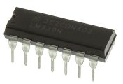
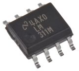
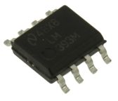
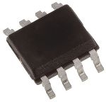
Mounting Types
Comparators can be found in both surface mount and through-hole mounting configurations to enable use in a wide variety of applications.
Comparator power supply types
Available in both single and dual power supply configurations, a comparator can easily be implemented into a robust solution.
Various package types, pins, sizes, channels per chip, PSRR (power supply rejection ratio), CMRR (common-mode rejection ratio) are all available.
925 Producten voor Comparators
Op voorraad
Subtotaal (1 verpakking van 10 eenheden) € 2,88(excl. BTW) € 0,288/eenheid |
Op voorraad
Subtotaal (1 eenheid) € 1,34(excl. BTW) € 1,34/eenheid |
Tijdelijk niet op voorraad
Subtotaal (1 tube van 100 eenheden) € 57,60(excl. BTW) € 0,576/eenheid |
Momenteel niet beschikbaar
Subtotaal (1 rol van 2000 eenheden) € 392,00(excl. BTW) € 0,196/eenheid |
Op voorraad
Subtotaal (1 verpakking van 20 eenheden) € 2,50(excl. BTW) € 0,125/eenheid |
Op voorraad
Subtotaal (1 verpakking van 10 eenheden) € 2,30(excl. BTW) € 0,23/eenheid |
Laatste voorraad RS
Subtotaal (1 verpakking van 20 eenheden) € 16,08(excl. BTW) € 0,804/eenheid |
Op voorraad
Subtotaal (1 eenheid) € 0,37(excl. BTW) € 0,37/eenheid |
Op voorraad
Subtotaal (1 eenheid) € 0,49(excl. BTW) € 0,49/eenheid |
Op voorraad
Subtotaal (1 rol van 2500 eenheden) € 415,00(excl. BTW) € 0,166/eenheid |
Op voorraad
Subtotaal (1 verpakking van 25 eenheden) € 3,475(excl. BTW) € 0,139/eenheid |
Op voorraad
Subtotaal (1 eenheid) € 1,36(excl. BTW) € 1,36/eenheid |
Laatste voorraad RS
Subtotaal (1 verpakking van 20 eenheden) € 17,88(excl. BTW) € 0,894/eenheid |
Laatste voorraad RS
Subtotaal (1 verpakking van 10 eenheden) € 5,87(excl. BTW) € 0,587/eenheid |
Op voorraad
Subtotaal (1 eenheid) € 1,33(excl. BTW) € 1,33/eenheid |
Op voorraad
Subtotaal (1 eenheid) € 0,78(excl. BTW) € 0,78/eenheid |
Laatste voorraad RS
Subtotaal (1 eenheid) € 0,91(excl. BTW) € 0,91/eenheid |
Op voorraad
Subtotaal (1 tube van 25 eenheden) € 22,55(excl. BTW) € 0,902/eenheid |
Laatste voorraad RS
Subtotaal (1 verpakking van 10 eenheden) € 1,22(excl. BTW) € 0,122/eenheid |
Op voorraad
Subtotaal (1 verpakking van 25 eenheden) € 16,80(excl. BTW) € 0,672/eenheid |


Populaire zoekopdrachten
Wees als eerste op de hoogte van onze nieuwste producten en aanbiedingen
E-mailadres
De persoonlijke gegevens die u aan ons verstrekt bij het aanmelden voor deze mailinglijst worden verwerkt in overeenstemming met ons privacybeleid.